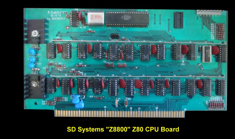
SD SYSTEMS - Z8800 CPU
Board.
This was SD Systems first S-100 card. As mentioned in the
history
section it was a very early Z80 card for the S-100 bus. The card had a 2MHz
crystal and a corresponding Z80 chip. A schematic of the final circuit is shown
here. In spite of the atrocious schematic diagram the circuit design was fairly
simple.

The card was designed to be a drop in
replacement for a 8080 CPU card in Altair and IMSAI computes. The card was sold
as a kit and had one slightly unusual feature of running the ground lines across
the front of the board with two vertical metal strips. This was a time when most
boards had only 14 and 16 pin TTL chips so all bus drivers were 8T97's. Likewise
discrete resistors were used to pull up lines to 5 volts. Nevertheless the two 7805
voltage regulators were more than adequate to handle the boards needs. There was
no on board ROM or anything else for that matter it was meant to be a direct Altair/IMSAI
replacement. There were some minor differences however.
The "Stack" and "Interrupt Enable" panel
lights were continually lit on front panels. These signals were not provided
by the Z-80 (or any Z-80 CPU card), therefore these lights were always lit.
Also the Address lights did not "flicker" in the same manner as with a 8080A card
during a program "RUN". This was due to the slightly different timing that the Z-80
exhibits on the address and data lines. This difference were visual only,
and were of no practical concern. For users of the Processor Tech VDM video board
with this board the VDM required a slight modification. This mod is necessary
because WR occurs one "T" state earlier in the Z-80 than on the 8080A. The
user had to disconnect PSYNC from the VDM board. This causes the VDM to strobe
the memory and port address comparator once every "T" state as opposed to once every
"M" state. This mod did not affect the normal operation of the VDM when used
with the Z8800 or an 8080A CPU. The mod was as follows: Remove IC 18 (74LS132) from
its socket. Bend Pin 5 up and replace IC 18 making sure Pin 5 DOES NOT make contact.
When DMA devices such as the
Cromemco Dazzler were used with the Z8800 CPU, a modification was needed.
The trace going to Pin 1 of IC 19 should be cut and Jumpered to Pin 8 of IC 19,
This insures the CPU clocks will be on the buss during DMA cycles. SD Systems
supplied a brief but excellent comparison between the differences between the operations
of an 8080 and Z80. They can be seen
here.
Other SD Systems S-100 Boards
8024 VDB
ExpandoRAM
ExpandoROM
SBC
VersaFloppy I & II
Z8800
PROM-100
I/O8 Serial Board
4KRAM
Other Boards
This page was last modified
on 01/08/2011


